Compaq Presario Hinge repair
Unfortunately, I own an old Compaq Presario 700. It is a POS, and I will never own another Compaq product.
If you are unfortunate enough to own a Compaq laptop, you may find this page useful.
The Problem...
Do you own a Compaq Presario 700Z, that has bad hinges? In other words, the screen no longer has any resistance, and just falls over? And before they failed completely - it used to be free for 10 to 20 degrees before it had friction? Here is how you can repair the POS for less than $10.
Compare that to the this conversation I had with Compaq support.
Me: "I would like to buy new hinges for my Compaq Presario 700Z (which is only 2 years old, and shouldn't be broken yet)"
Them: "Sure, let me get you a part number."
Them: "Here is your part number (don't remember the actual number), go put it into this website to order it."
Me: "I just put it into the website, and it says that it costs $290. What the heck is that?"
Them: "The price for an entire new screen."
Me: "Congratulations. You have just insured that I will never buy another Compaq anything in my life"
The Repair
It turns out on my hinges, the friction generating half of the hinge was still fine. On the other half of the hinge, the round pin has a flat top, which is not supposed to turn inside of the sleeve on the other side. However, it had ground out enough of the sleeve that it could now turn freely in the sleeve. So , I went and got some JB Weld (or an equivalent epoxy) (which you can get at nearly any hardware store very cheaply). You will also need a T8 Torx driver to remove all of the screws on the laptop.
Next, you will have to take apart your laptop. I found an entire manual listed on this website that has step by step instructions for taking apart (and reassembling) Compaq Presario 700's. I copied the entire manual to my web site just in case it happens to disappear.
Step 1: Back up all of your data! If you break something, your laptop may never turn on again. So back everything up first.
Step 2: Follow the instructions for removing the display, with the following exception: You don't need to unplug the cables from the display. They are long enough that you can just leave the display laying on the table behind the laptop.
If you do decide to remove the display entirely, you may find that you have to remove the heat spreader in order to get the cords unplugged for the display. If you do this, you *must* remove the old thermal compound from your processor, and buy new thermal compound to put on it before you put it back together. When I did this to mine, the laptop would only run for 30 seconds before it shut off until I bought some new thermal paste. Now it actually runs cooler than ever.... their original thermal pad was a real piece of crap.
Step 3: Take the cover off of the display. Do this by removing all of the rubber pads, then removing the screws under the pads. There are 6 total, each of the 4 corner pads, and then two more at the outside edges of the wide pad on the top. Now pry off the cover (it has some catches, but it should come off without breaking). I don't recommend using a screw driver or anything, you may damage your screen. Just work it off gently by hand.
Step 4: Remove the hinges from the screen. There are only 2 more screws holding them on - but you will also have to remove the screws from the sides of the lcd panel so you can raise it up enough to get the hinges out.
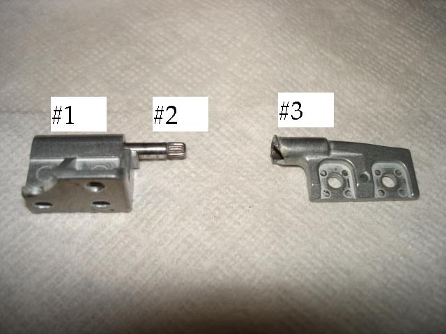
Step 5: A guy named Pumin Wuvanich was nice enough to send me a picture to help explain this part. Pull the hinges apart (so you have the friction generating part with the pin still in it (#1 and #2 below), and then the sleeve (#3 below)). The friction generating part is simply about 24 tiny metal disks that are slid over the shaft. You do not want to freeze this part (#1 and #2) - this is where it is supposed to turn. The part you want to freeze is where the pin just goes into the sleeve (#2 into #3). This end of the pin also has a flat spot on it - at least mine did. It appears that in the photo below, this hinge had a spline, instead of a flat spot. Maybe they replaced their bad design with a different (but equally bad) design at some point.
Step 6: Slide a small piece of paper over each of the pins - this will keep any extra epoxy from running down into the friction generating part - #1.
Step 7: Put some JB Weld into the sleeve (#3), and on the pins (#2). Do not get any into the friction generating area (#1).
Step 8: Push the hinges back together, and clamp them tight (so they don't slide back apart). Make sure you have the pin *all* the way back into the sleeve (otherwise you will not be able to put it back together)
Step 9: Let sit for a day.
Step 10: Tear off as much of the excess paper as you can, and then reassemble.
Congratulations, you just saved over $300 dollars.
Alternate repair
A guy named Joel Frigon suggests the following, as a quicker repair method. The concept is the same, but the technique is a bit simpler - you don't have to take as much apart, and it is quicker.
1. Remove the LED and switch panel between the keyboard and the display. (Gently pry up after removing the screws on the back)
2. Using a small Torx bit remove the two screws that hold the hinge decorative covers.
3. Close the cover and pry up the part of the decorative hinge covers that protrudes out the back of the computer.
4. With the cover closed gently pull the decorative hinge covers over the hinges.
5. Open the cover about 90 degrees and position the CD ROM drive up. The cover and base will form an "L" and the computer
will stand up with the floppy drive down and the CD ROM up.
6. Get some crazy glue from Radio Shack. Don't use any other brand. Notice that the hinge has three parts. As you look at
the lower hinge the upper part provides the friction. A shaft connects the upper and lower parts. The lower part is supposed
to be fixed to the shaft but it is actually slipping. Place a drop or two of Radio Shack crazy glue on the shaft between the
upper and lower half. Gravity will pull the glue into the lower part and fix it to the shaft. Don't move the cover. Leave the
computer in this position for about 15 minutes.
7. Now it is safe to invert the computer so that the Floppy is up and the CD ROM is down. Again apply glue to the shaft and
allow it to run down into the lower half of the hinge. After about 15 minutes it will be safe to move the cover.
8. Replace the decorative hinge covers, screws and LED/Switch panel.
9. Enjoy your repaired computer.