 |
- Remove the following components:
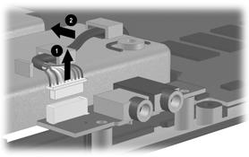
- Disconnect the audio cable 1 from the audio board
and remove the cable from the clips 2 in the base
enclosure
|
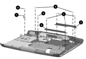 |
- Remove the following components:
- four silver TM2.5 × 6 screws 1 that secure the front and rear
optical drive alignment rails
- front 2 and rear 3 optical drive alignment rails
- two silver HM5 × 22 standoffs 4
- one silver HM5 × 11 standoff 5
|
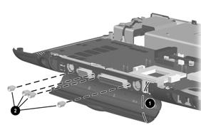 |
- Position the computer so the rear panel faces forward.
- Open the plastic cover 1 to reveal the connectors.
- Remove the four silver 5mm screwlocks 2 on each
side of the parallel and serial connectors.
|
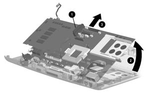 |
- Position the computer so the front faces forward.
- Use the optical drive connector 1 to lift the
front of the system board 2 until it clears the base
enclosure.
- Slide the system board forward 3 and remove it
from the base enclosure.
|
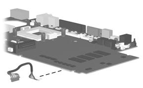 |
- If necessary, disconnect the audio cable from the system board
|